In a previous post, I talk about a new amp project. Since this post, I bought several stuffs to build it. But while looking for parts, I talk with several people. And they convince me to build a push-pull instead of a single-end.
So, I got 4 outputs transformers (2 SE and 2 PP), I gonna try the PP first, and if this work great perhaps, I will sell the single transformers or build a second amp.
The main difference between single-end and push-pull, is distortion. In fact, SE produce a lot of harmonics, so a lot of distortion. Beside this is a bad idea for a power amp, this is really what a lot of people call a “real tube sound”. Anyways let’s start with a full featured push-pull, and perhaps came back to a simple SE just for the fun.
The main issue right now, is that push-pull are a lot of more complicated. I mean you can build a simple SE with only a spare components.. this is not the case of a push-pull. For a single channel, I need 2 tubes, 1 bias power-supply, a highly regulated power supply and a phase shifter ..
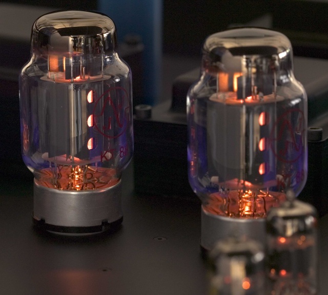
For the tubes, I decided to use some KT88. In fact, a friend give me a spare matched quad of NOS (plain old) Gold Lion tubes + the needed output transformers so .. This tube are really great for the HIFI. And they look really great !!!
For the input stage, I decided to do something not really common. In fact most tube amps use some ECC82 / ECC83 for the input stage. My choice is something little different cause, I want to use some bigger tube. A lot of people say the 6SN7 (or 12SN7) are great for this stuff too. And some high quality power amps tube this, so why not. After looking for a while for a good schematic, and tested severalls stuff, here the one I gonna build:
In the comming (soon I hope), I will describe the schem and the modification I made. Right now, I’m waiting for the power transformer (comming from US take a long time). In a next post, I will post some photos of my input test bench …
Enjoy light ?
Hello,
Nice electronics page. I’m also looking into building my first tube amp and have been looking for a good schematics. Could you kindly provide a link to the webpage that have this schematic? This is by far the best-looking schematics I’ve seen. Thanks!!
ps. if you could, please reply to my email @ paul.p.pan@gmail.com. Thanks again.
regards,
Paul
Hello et Bonjour!
Perhaps you should look for a simpler bias system to safe cash and simplify things. Cathode bias = No bias adjustment when you swap tubes! I recommend a fender deluxe 5Y3 circuit with cathode bias, there is no fixed voltage supply to the grids, the cathodes are grounded. Substitute rectifier tube with silicon diodes, or switchable recto. Tube rectifier in double-end amp = power supply sag = sustain. Very loud for a hobby amp.
I’ve built a few SE amps from scratch, but would recommend using an old chassis from a 50′s radio as a good starter project as well. I am planning an amp in an old mono radio phono unit, SE with all transformers in place, $25 at the auction. It will be the amp/record playing computer desk! anyways, good luck and merci pour l’anglais.
I have built the same amp excluding the second tube. I am using plitron power transformer along with Hammond power out put transformer.No hum the sound is ok little low on power. I will check it at 1khs and 1.5 volt input signal. On a fixed load of 8 ohms. The tube compliment is two 6550 per side and one 12au7 as a driver. There is no feed back applied.A simple switch can be applied to convert this to a triode or ultra linear.Expensive project will last for a long time.Svetlana tubes and solen caps.
Hi,
Nice design. I started building P_P screen tapped amps with EL34′s and 5881′s
back in the late sixties. I’m now looking at doing something with sextet or octet P-P
6550′s and custome toroidal transformers or making the transformers my self.
Questions: Have you looked at toroidals and why did you choose a 33% screen tap as
opposed to 40% (more common)? What are your feelings about fixed bias vs. cathode
bias? By the way, I still have the old 6SN7 / 5881 and 6SN7 / EL34 amps. They still
work 40 years later. I still beleive in Altec 511B’s and 802D’s and EV T350′s
Hi;
I have a few questions:
1.Did you ever got around building this project?
2. I understand that this design is based on Plitron special transformers. Specifically, the output transformer is not using all secondary connections. However the Hammond transforms require that all secondary links to be used (according to data sheet). did you look into it?
3. did you consider adding voltage regulation to the power supply part?
Regards
Doodoo:
1) Nop, not started yet .. i’m really to busy.
2) The transformer is quite normal .. (33% tap instead of 43%, but this is just a matter of polar) .. Hum for hammond the schematic is fine I think.. (no matter what the datasheet say)
3) I’m considering adding voltage regulation for the first stages .. yes. For the KT88 this isn’t do-able .. but for the rest, this can be done easily I think.
Bye
HI,
Great design for KT88 push-pull.
I got a Single-ended output transformer.
Got sugestions or site for parallel KT88 single ended amplifier?
Regards,
Ashby
Nice schematic, it will be fine i think. What about the power supply schematic?
Jan 10th 2009. Build the same amp excluding the second driver tube as mentioned in my previous comment. Caution for every one. I tried to check the voltage without the tubes. Voltage readings were measured it was all ok. The second day i wanted to re arrange some of the wires at the kt88 sockets at pin #5 pin. I did get a shock at this point. A warning to all the diy please discharge the .22uf Caps and the high voltages at all points. My second tube ia a 12bh7. I hope this will benefit all of you.Thanks
I would like to know if any one has the power supply schematic. At present . I have used a plitron transformer..
I recently made a line preamp and I also incorporated a timer with relays to control the out put after 60 seconds to prevent a thump at the speakers. preamp parts cost around $ 10 Canadian this is excluding the power supply. All toll the cost was around $150 including the enclosure.