J’ai décidé de rédigé cet article en français, une version anglaise devrait suivre ..
Il y a peu, notre lave linge Laden (FL1281) est tombé en panne. Symptômes : Il ne s’allume plus du tout, aucun voyant de la facade ne s’éclaire, et aucun bruit .. rien. Il vient tout juste d’avoir 3 ans. Il s’avère (je vais le découvrir par la suite) que c’est une panne connue et visiblement très courante.
Vu le prix de la bête, et son âge, je décide de l’ouvrir en me disant que cela ne doit pas être bien grave, un fusible, un fil coupé ? Il n’y a donc pas de fusible, étrange, en même temps la norme NF C 15-100 (bâtiment) dit que l’on doit avoir un fusible séparé pour le lave linge donc .. why not. Le 220v est bien présent jusqu’au bornier du panneau de commande.
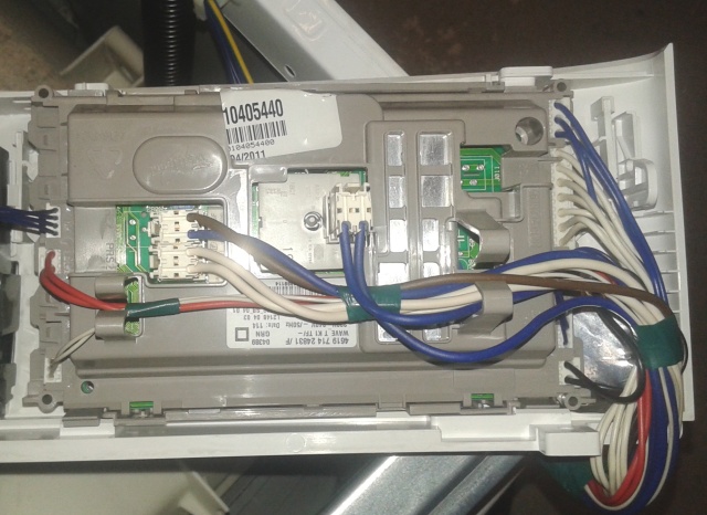
Panneau frontal Whirlpool FL1281
En démontant le panneau on constate plusieurs choses : La carte électronique porte une référence spécifique Whirlpool; rien ne semble avoir brulé; l’arrivée du 220v est raccordé directement sur le sélecteur principal qui sert de bouton ON/OFF. Cela évite d’avoir une alimentation pour gérer cela, mais nécessite un sélecteur assez sécurisé (ca me choque un peu, et le sélecteur coute du coup, une blinde).
Après quelques tests de continuité, tout semble Ok, le sélecteur fonctionne, il faut donc suivre les pistes, à la sortie du sélecteur on trouve une grosse résistance de 3w nommée R020 (la bien aimée). Elle est HS, elle a donc fait office de fusible.
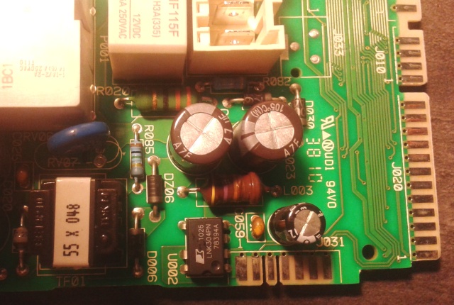
R020 + LNK304PN
Cette résistance sert en fait à abaisser la tension 220v (et faire fusible au besoin), avant d’attaquer un régulateur à découpage tout intégré 220v AC =>12v DC : LNK304PN. Il y a très peu de régulateurs permettant de faire cela sur le marché avec si peu de composants externes. On notera que Whirlpool dans son extrème bienveillance a quand même pris la peine d’ajouter un tranformateur d’isolement en sortie du LNK304PN. Après un test rapide, je m’aperçois bien entendu que le LNK est HS. (court-circuit entre la patte D entrée et les pattes S)
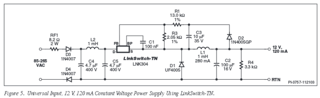
Schéma d’utilisation typique d’un LNK304PN (datasheet)
Je commande donc les composants suivants chez RadioSpares (les seuls à avoir des LNK304PN en stock). La résistance, la self (par sureté), le régulateur.
- Résistance oxyde métallique 33R 3W (code RS : 2142550)
- LNK304PN, 12V dc, PDIP (code RS : 5254151
- Inductance traversante Epcos, 470uH, 280mA (code RS : 1911169)
Bilan 10.86 € livraison comprise pour 5 jeux complets. Deux jours plus tard, je change le tout, je remonte, ça repart! Banco, Madame est contente, et nous avons économiser 230€. En effet, après recherche, la carte électronique se trouve en SAV pour 145€, il faut à cela rajouter 50€ de frais de programmation. La carte est utilisée sur pleins de modèles de lave ligne Whirlpool, il faut donc programmé une petite EEPROM en fonction du modèle de la machine (Whirlpool, Laden ..) On ajoute à cela les 35€ de main d’oeuvre, et le compte est bon.
Mais pourquoi ? Je me suis tout de suite demandé pourquoi avoir utilisé ce régulateur étrange qui semble être fragile. En fait, en cherchant sur Google, on se rend compte qu’il est utilisé sur quasiment tous les modèles de lave-linge, sèche-linge et lave-vaisselle récents de la marque et que visiblement je ne suis pas le seul à avoir des soucis : https://www.google.fr/search?q=whirlpool+R020&tbm=isch !!
Ce composant a deux avantages majeurs. Il coute quasiment rien, moins de 1€ et remplace un transformateur classique coutant au moins 3 fois plus (et aussi bcp + gros). La référence est stable; il existe des tonnes de régulateurs chinois faisant la même chose (en plus complexe), mais ils ne sont pas pérennes.
En conclusion, en voulant gagner qques euros sur le prix d’un lave-linge à 400€, Whirlpool vend des produits dont la durabilité semble très aléatoire. Une simple surtension suffit à rendre le produit “bon pour la poubelle”. Il ne faut pas se tromper à 230€ la réparation, je pense que la majorité des produits finiront à la déchèterie au bout de qques années (3 c’est pas bcp quand même). De mon côté, j’ai sourcé le 5 jeux de composants, j’ai donc encore droit à 4 pannes ;)
Aimer la lessive ? non pas vraiment
Update 1: Vu le nombre de commentaires, je ne suis clairement pas le seul à avoir eu des soucis avec ce lave-linge. J’attire votre attention sur le fait que la manipulation n’est tout de même pas si évidente qu’elle en a l’air. De nombreux lecteurs ont rencontré des problèmes pour dé-souder le LNK. En effet, les énormes pads thermiques au niveau des pattes n’aident pas du tout. Une solution simple et efficace consiste à couper les pattes du LNK avant de les dé-souder. Perso, j’ai utilisé une pince coupante, mais un bon coup de Dremel au milieu du composant fera également l’affaire.
Update 2 : Au final mon lave-linge a rendu l’âme en début d’année. Il avait presque 5 ans.. Les paliers au niveau du moteur / tambour s’usent, et bien entendu, on ne peut pas les changer. Il faut donc changer tout le bloc tambour, ce qui n’est pas du tout viable économiquement.
Je ne connais pas la durée de vie des lave-linges WhirlPool, mais clairement ce Laden n’auront pas donné bcp de satisfaction. Nous avons décidé de changer pour un modèle Samsung, à voir dans le temps ce que cela donnera.
 Tout cela semble bien merveilleux, sauf que les journalistes ont la mémoire un peu courte. L’un des premiers objets connectés vendu fut bien le