Howto hack USB port on a LG LAC-M6500R MP3 Player (CD/Radio/MP3 Player)

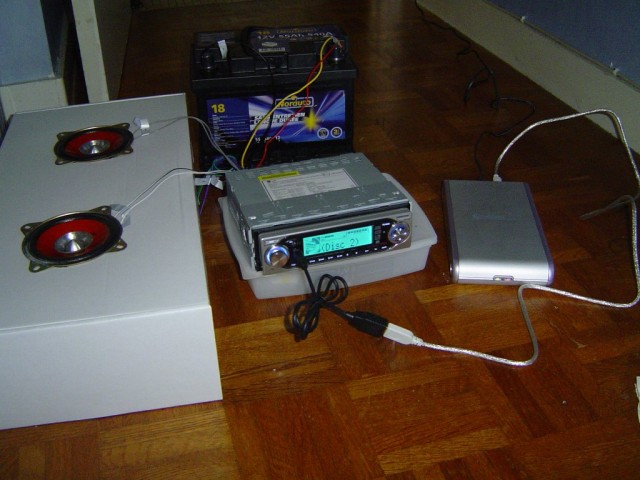
Some friends buy me a nice MP3 player for my car last year (birthday): LAC-M6500R

This stuff looks great and you can even plug a hard-drive. The main issue is that the firmware only support 999 files on a single USB device, so that’s enougth for ~4Go of MP3 but not more. So I decided to buy some USB sticks, it’s far more simple .. no external power supply, and just the room to place a quite large MP3 collection (simply buy 2/3 sticks and that rules)

http://jkx.larsen-b.com/photos/Electronic/DSC02235.sized.jpg

That’s ok, but hum, as you can see on this picture the USB plug is on the front panel. And that’s a mess, cause you have to unplugged it when you want to remove the front panel (some infamous guys already try to open my car 4 times..), or to put a CD in. Beside this is a gift, I decided to open it, and try add a external USB in the back. I think my friends will understand this: “If you can’t open it, you don’t own it” ..

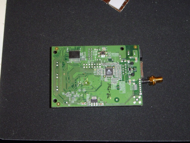
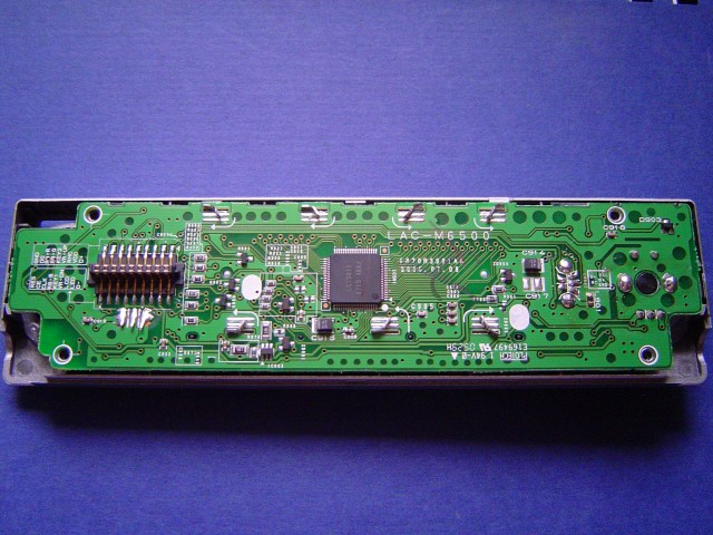
First, I decided to open the front panel, to look how the USB plug is connected. As you can see on the aboves pictures, the USB power-supply come form the main board.

http://jkx.larsen-b.com/photos/Electronic/DSC02242.sized.jpg
http://jkx.larsen-b.com/photos/Electronic/DSC02541.sized.jpg

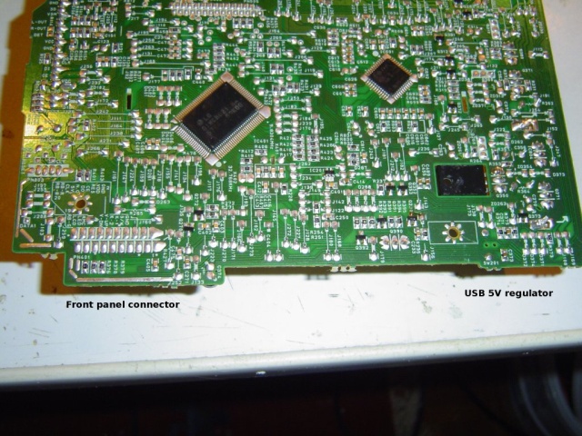
That’s fine.. We simply have to add take the power from the source ..

http://jkx.larsen-b.com/photos/Electronic/DSC02542.sized.jpg

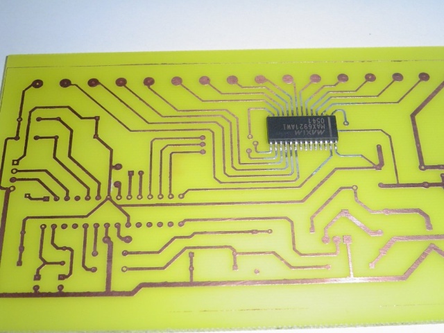
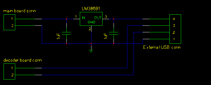
When I look closely, I discover that the PSU provide 5.5v instead of 5.0v. The main reason, is that the front panel contain a small chips do the final regulation.. Ok, we can do the same ? :) I used a low drop 5.0v regulator: LP38691 with 2 small caps..

http://www.national.com/images/pf/LP38691/20126501.jpg

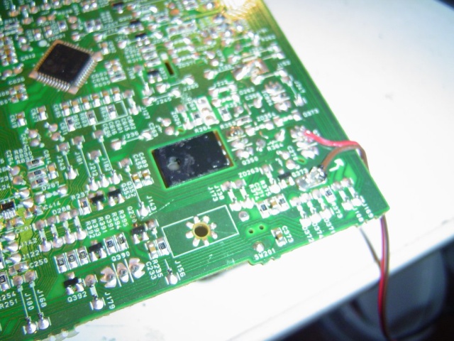
The final step, is to connect the data bus (DATA- / DATA+), this was really hard, because the front panel USB bus is connected to the main decoder board throught a small wire. As I’m not able to find the right plug, I decided to solder it on the board ..

http://jkx.larsen-b.com/photos/Electronic/DSC02553.sized.jpg

So we have something like this:
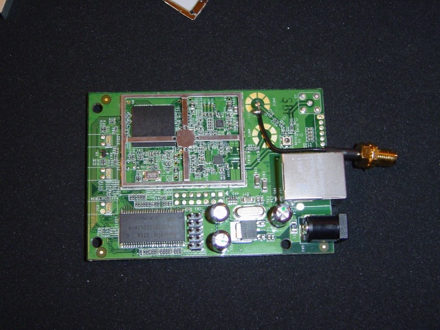
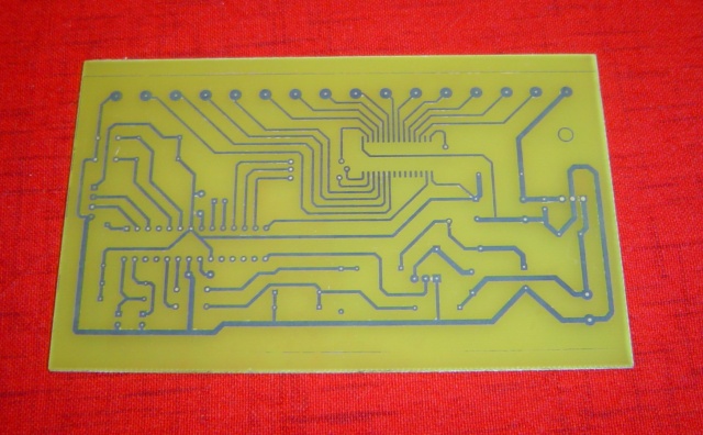
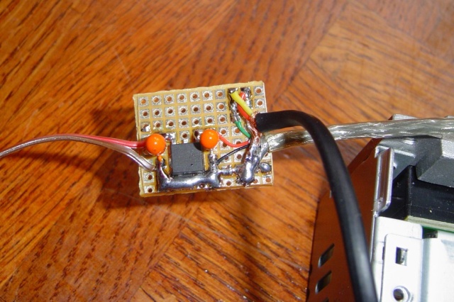
http://jkx.larsen-b.com/photos/Electronic/LG_gschm.png

The small PCB:

As you can see on this picture, on the left, there is the wires from the main board, and the 5.0v regulator. On the right the wire that goes to the decoder board, and the external new USB connector.

http://jkx.larsen-b.com/photos/Electronic/DSC02551.sized.jpg

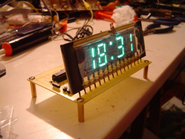
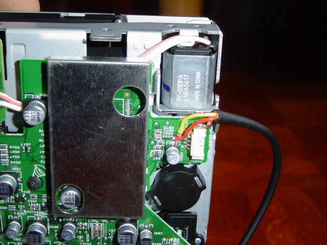
Here the finished product:

http://jkx.larsen-b.com/photos/Electronic/DSC02558.sized.jpg

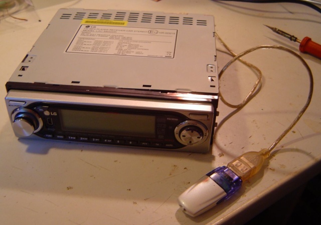
Ok, that’s fine, now, you can place this small board in system (there is a lot of room), and enjoy the external USB cable ;)

Dell Truemobile (D400/D410/D600..) wifi driver on Linux (BCM4309)

It’s time to get quit ndiswrapper to use something little more open. I decided to test the latest Broadcom bcm43xx driver on my Debian system. This seems to work fine, and is really simple to install (unlike ndiswrapper)

So, first build your kernel > 2.6.17) (I used a 2.6.19) with support for the bcm43xx enabled. “Device Driver/Network support/Wireless”. The next step is a little shorter, simply install bcm43xx-fwcutter (via apt-get of course). This will ask you if you want to download the required firmware, and of course you will answer yes.

Now, is time to reboot, and discover the results:

bcm43xx: Chip ID 0x4306, rev 0x3
bcm43xx: Number of cores: 5
bcm43xx: Core 0: ID 0x800, rev 0x4, vendor 0x4243, enabled
bcm43xx: Core 1: ID 0x812, rev 0x5, vendor 0x4243, disabled
bcm43xx: Core 2: ID 0x80d, rev 0x2, vendor 0x4243, enabled
bcm43xx: Core 3: ID 0x807, rev 0x2, vendor 0x4243, disabled
bcm43xx: Core 4: ID 0x804, rev 0x9, vendor 0x4243, enabled
bcm43xx: PHY connected
bcm43xx: Detected PHY: Version: 2, Type 2, Revision 2
bcm43xx: Detected Radio: ID: 2205017f (Manuf: 17f Ver: 2050 Rev: 2)
bcm43xx: PHY connected
bcm43xx: Microcode rev 0x127, pl 0xe (2005-04-18  02:36:27)
bcm43xx: Radio turned on
bcm43xx: Chip initialized
bcm43xx: 30-bit DMA initialized
bcm43xx: Keys cleared
bcm43xx: Selected 802.11 core (phytype 2)

Fine no ? this works really fine right now, but I need to do some extended check before.

Enjoy FakeMobile

DIY KT88 + 6SN7 push-pull Amp / Part 1

In a previous post, I talk about a new amp project. Since this post, I bought several stuffs to build it. But while looking for parts, I talk with several people. And they convince me to build a push-pull instead of a single-end.

So, I got 4 outputs transformers (2 SE and 2 PP), I gonna try the PP first, and if this work great perhaps, I will sell the single transformers or build a second amp.

The main difference between single-end and push-pull, is distortion. In fact, SE produce a lot of harmonics, so a lot of distortion. Beside this is a bad idea for a power amp, this is really what a lot of people call a “real tube sound”. Anyways let’s start with a full featured push-pull, and perhaps came back to a simple SE just for the fun.

The main issue right now, is that push-pull are a lot of more complicated. I mean you can build a simple SE with only a spare components.. this is not the case of a push-pull. For a single channel, I need 2 tubes, 1 bias power-supply, a highly regulated power supply and a phase shifter ..

For the tubes, I decided to use some KT88. In fact, a friend give me a spare matched quad of NOS (plain old) Gold Lion tubes + the needed output transformers so .. This tube are really great for the HIFI. And they look really great !!!

http://jkx.larsen-b.com/photos/TubesAmps/KT88.sized.jpg

For the input stage, I decided to do something not really common. In fact most tube amps use some ECC82 / ECC83 for the input stage. My choice is something little different cause, I want to use some bigger tube. A lot of people say the 6SN7 (or 12SN7) are great for this stuff too. And some high quality power amps tube this, so why not. After looking for a while for a good schematic, and tested severalls stuff, here the one I gonna build:

http://jkx.larsen-b.com/photos/TubesAmps/canal.sized.gif

In the comming (soon I hope), I will describe the schem and the modification I made. Right now, I’m waiting for the power transformer (comming from US take a long time). In a next post, I will post some photos of my input test bench …

Enjoy light ?

Unleash Nabaztags or Die !!!

http://www.blogsmithmedia.com/www.engadget.com/media/2006/09/nem006.jpg

I’m a proud owner of a nice Nabaztag/tag since a while (gift from my mother for my birthday). Like most other tags around, mine works sometimes, but yeah I have some issues to use at the full power. The weather stuff for example is really buggy.

Not even talking the extra-fee to simply send a message to the tag !! So like many others, I hope silently that my little rabbit will soon use a opensource stuff, instead of the “full-of-bug” and “miss-feature” Violet website.

Come on and play: http://nabaztalk.com/forum/viewtopic.php?pid=4322

Common Violet unleash the tags

Howto to a delete lot of Zope/Plone/CPS User account ?

In a previous post, I study the way some spammers use plone user folder to spam my blog. But this time, it’s my turn. I host since a little time right now, a small CPS
website for my work. And I discovered a lot of spammer user account on it.

The main issue, is that I haven’t unset the “joinable” flag, so everybody can create a account. By the way password are sent, spammers doesn’t manage to post stuff in the personnal area.

With 300 users, and only 4 valids, I need to find a way to clean the acl_user folder. Last time I used twill, this works really great, so I decided to use the same stuff for Zope.

Here my little script:

#!/usr/bin/python

LOGIN='foo'
PASSWORD='far'

LOGIN_URL='http://your_server/manage_main'
USER_URL='http://your_server/acl_users/manage_users'
GOOD_USERS = ['jkx','foobar']

import twill

def delUsers():
   twill.commands.go(USER_URL)
   form = twill.commands.showforms()[0]

   usernames = form.possible_items('names:list')
   for u in usernames:
      if u not in GOOD_USERS:
         twill.commands.formvalue(1,'names:list',u)

      twill.commands.showforms()
      twill.commands.submit(3)

def doLogin():
   twill.commands.go(LOGIN_URL)
   forms = twill.commands.showforms()

   twill.commands.formvalue(2,'__ac_name',LOGIN)
   twill.commands.formvalue(2,'__ac_password',PASSWORD)
   twill.commands.submit()

if __name__ =='__main__':
  doLogin()
  delUsers()

This will drop all user account (not the ones in GOOD_USERS) ..

Scope clock / Round 0

Ok, everybody know I’m a clock builder right now ;) .. So beside I have a lot of stuffs to do, I decided to build a new clock.

A good friend, give a old Mullard DH7-11 tube, so it’s time to give it a try no ? ;) The main issue right now, is to find the power transformer to light this big guy

http://www.webx.dk/oz2cpu/clock-scope/dh7-clk.jpg

Finding old part is always hard, but the best thing is to keep on trying. I finally found a transformer builder at great price on eBay.

400v / 5mA transformer isn’t really common, you know.

For everybody who want to know what a scope clock is check this.

Enjoy Ray ?

Fonera motherboard pics, and more

Here some photos (hi-res) of the Fonera, the Fon routeur. This little box has:

  • 8Mo
  • Atheros CPU + Wifi

Here you can see the AR2315 CPU from Atheros. One stuff really funny, they decide to use exactly the same layout as the Atheros design (look at the pic closely). You can see the 16Mb Ram on the left. Just near the serial port, and the 14 pins header is a JTag. We can see the antenna, the network plug, and the power supply on the left.

You can find hi-res pics here

http://jkx.larsen-b.com/photos/Electronic/DSC02545.sized.jpg

Here, you can the 8Mo serial flash made by ST. And the Altima network chip.

http://jkx.larsen-b.com/photos/Electronic/DSC02547.sized.jpg

This looks like a great hardware to hack… some, and have a OpenWRT port. But it seems to have a really limited free GPIO and the BGA package doesn’t help :(

IVL1-7/5 Russian Vacum Tube (VFD) Clock – Part 1

I’m now building another clock with a IVL1-7/5. In fact, I’m preparing a large bench of VFD clock, and I need to test several stuffs, so the schematic isn’t public right now.

This one use quite the same stuff than my previous I IV-18 clock, the main difference is the VFD power supply, but if you read this weblog, you will understand easily. I will publish the whole design and source code for free soon.

Anyway, here some pictures:

http://jkx.larsen-b.com/photos/VFDProjects/DSC02522.sized.jpg

The PCB made with toner transfert

http://jkx.larsen-b.com/photos/VFDProjects/DSC02524.sized.jpg

Soldering SOIC isn’t that hard ;)

http://jkx.larsen-b.com/photos/VFDProjects/DSC02530.sized.jpg

The beast

http://jkx.larsen-b.com/photos/VFDProjects/DSC02528.sized.jpg

The VFD tube is really big, and nice no ?

http://jkx.larsen-b.com/photos/VFDProjects/DSC02531.sized.jpg

As you can see on the latest picture, there is a little gradian due to the filament supply. I haven’t find a simple to use (as the MAX6921) VFD driver that support AC filament. (MAX6931 is to small for hands soldering)

Enjoy :)

DivShare automatic upload script (with twill)

DivShare is the latest share website a la mode ;) I started to use it quickly, and like it a lot. You can upload files really fast, and without any loging or password. It sound usefull no ?

The only issue is that you need a web browser on the desk, and waste some time to find the file. We can do a lot of better with command line no ?

So, I decided to use Twill to build a small tool to do the automatic-login, and file upload. (You can use anonymous login too, simply add -a to the command line)

Of course, a little example is better no ;)

jkx@localhost /tmp> divshare.py ./divshare.py
=[ DivShare uploader script ]=
   * Already logged

http://www.divshare.com/download/21679-c72

You can upload up to 5 files at one time, and on course you can script it .. (everybody love find ?)

In the way of, eating it’s own dog food, I decided to host the script divshare.py on
DivShare :)

Anode power supply for VFD display ( 5v to 80v stepper PSU )

For my next project (another VFD clock ;), I need a small variable PSU. The main issue with the VFD display, is the power supply. In fact you need 2 differents PSU:

  • a 5v / 100mA for the filament
  • a variable 20 to 75v for anodes..

VFD tube like the IV18 need something like 20/30 volts in direct drive and 50/70 volts where they are muxed. As I can not use them in a direct drive, I need a psu that support output from 20 to 75v, by this way, I can dim the display easily and test the whole stuff in a direct.

I already have done several nixie PSU, but this time I want to build something small (doesn’t cost a lot) with really common parts. I decided to look at smaller mosfet, and I found the BS107 .. small TO92 package and 200v ;)

Here the schematic:

http://jkx.larsen-b.com/photos/VFDProjects/vfd_psu_schm.png

With this simple stuff, and a little microcontroler, you can step the output easily. You can use a 220uH inductor with a 5v VCC, or a smaller one 100uH if you have a PSU between 6v to 15v.

/Enjoy the next step