I’m now building another clock with a IVL1-7/5. In fact, I’m preparing a large bench of VFD clock, and I need to test several stuffs, so the schematic isn’t public right now.
This one use quite the same stuff than my previous I IV-18 clock, the main difference is the VFD power supply, but if you read this weblog, you will understand easily. I will publish the whole design and source code for free soon.
Anyway, here some pictures:
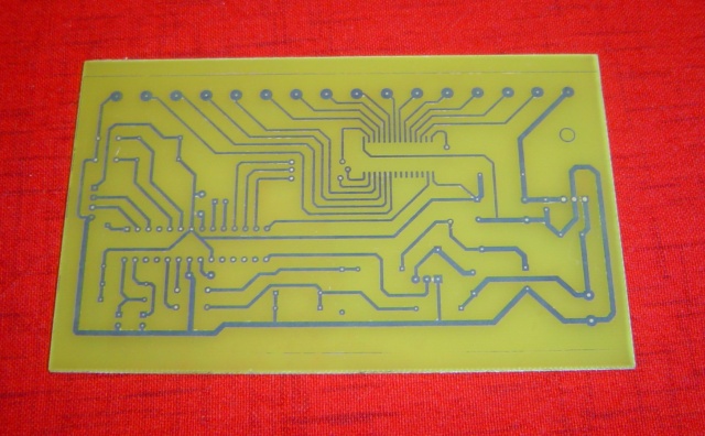
The PCB made with toner transfert
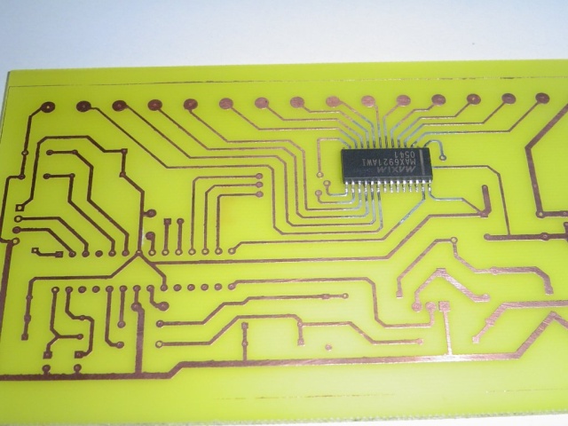
Soldering SOIC isn’t that hard ;)
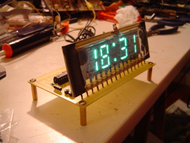
The beast
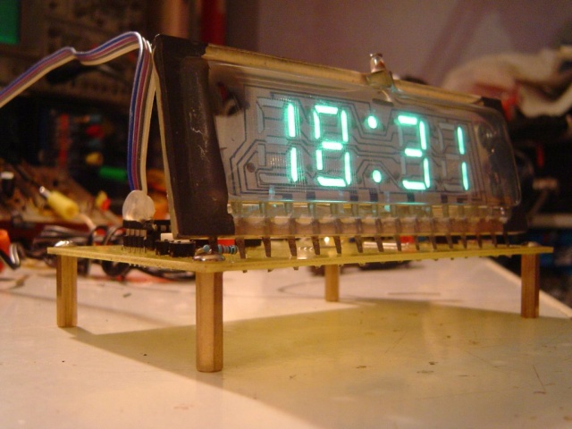
The VFD tube is really big, and nice no ?
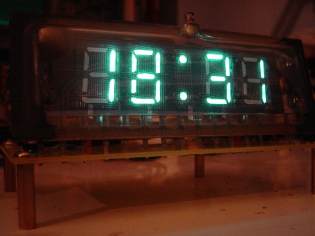
As you can see on the latest picture, there is a little gradian due to the filament supply. I haven’t find a simple to use (as the MAX6921) VFD driver that support AC filament. (MAX6931 is to small for hands soldering)
Enjoy :)
Hi jkx,
I created a link to your image (DSC02528.sized.jpg) to show people that visit my site what a VFD display looks like. I hope you don’t mind.
Kind regards,
Lex
http://www.kampherbeek.nl/Lex.html
Hello!
I have found Your site, searching for these russian clocks. I have had one in my younger ages and loved, so i decided to get one. i am really surprised, how much are there around, what variety (imy one was a wood-boxed, really good looking one) and nonetheless, they are in still working condition after 30 years of service. I have found a green little monster for myself. What is seems common with these clocks, the suplly’s capacitor. Altought it is russian, BIG in size and just 100uF, it dries out in 30 years dramatically, making the display flickering and unability to adjust anything. After replacing, a good-looking tube looked on me, showing some more usage, as the ends have more black evaporation on them and the digits aren’t as homogenic.
Finding Your site, i decided to get an IVL18 once :-)) and reading Your words, i suspect You may have some spare IVL1s. I would like to ask if You sell them.
Other words about filament. I have little expereince about VFDs, as i have only one own-built BG189Z-based display working in my ampilfier and some more tubes awaiting for use in my preamp/input selector, with some more attractive displaying. And, beside that, i have repaired some more displays. I found that the BG189Z wich has arrived in a prepared kit, has only a single 12V supply, wich was a bummer: The tube has a very gradient light, almost useless and there was two resistors limiting current on filament, with very hot temperatures. I decided to brake up this solution and use AC, based on my past experience, where all VFDs have had AC supply for heating. I found this far more simple. The drivers are HA12019, they have almost nothing to do just swith the segments and that’s enough about them :-) . I just simply wired the filament on the AC, with only one thing to think about: AC must be rectified in half-bridge for the logics, if it would used in full bridge, the display still would have gradient with some 50Hz flicker. Grids are on fixed voltage, so nothing else to do with it, it just works, supply is now 15V, as it gives bright enough display to pass a filter, filament’s current now reduced to a level that it’s invisible (the originally set current made them visibly heat…No comment) yet enough to light up the segments corners also.
What i want to make clear about it. You mentioned those VFD drivers compatibility to drive on AC filament. What is the problem with it? HA12019 doesn’t mention it, it simply drives anything :-) .
I have that russian clock, maybe i can map its electronics now as i have a full working one. The logics seems far simple and easy to reconstruct.
First thanks for this long comment ;)
I have some spare IV-18, yes. But I guess you can buy some on Ebay, for a couple of bucks .. I bought only one of this IVL1-7/5 from a german seller. The price is a bit high, but he have a lot of stock, and lot of species :)
Clearly the best way to run a VFD display is to use a AC filament supply, for sure. If not you will see this kind of display gradient. The main issue with that, is the logic will have some trouble with that wiring. Sometimes the filament (which in a VFD is the “ground”) will be at +5v (for IVL1) and after -5v, so you will see some flicker. The easy way to fix this is to use a special AC filament driver, but Maxim’s one are to difficult to solder.
The second way I know is to use decal the logic supply (and ground) from the value of the filament. This way, you avoid the -5v on the logic output circuit. but you still have some flicker ..
I don’t see why the half bridge method (for logic supply) can fix this ? If you can explain, I will be happy.
Thank You for Your reply!
There are some hungarian pages, showing some more information about different VFDs. One of them: http://www.amiga.hu/amigos/boz6_gad/disp/disp.html You can see some interesting ones here :-) . And a second one, with some circuit diagrams: http://www.elektroncso.hu/cikkek/vfd.php Let me know, if You need something to be translated. There are some diagrams showing the effect of filament driving in different situations. I have mispelled some little things in my past comment, i was tired and now it looks like terrible :-) so i try to correct them. I am using now a half wave rectifying (not half bridge, uh :-D ) for the logics, because when i used a graetz, visible flickering has occured on one end of the tube (unfortunately i have no circuit diagram to confirm all connections, it was 10 years before.. But i think the filament was connected with both ends on the AC line, because the GND line has been cut on the display panel and after it has been reconnected for the current version). I always used full wave, so this solution was a remeberous decide for me :-) . Here’s a PDF for HA12010, wich is a linear driver (while HA12019 has log scale): http://www.alldatasheet.com/datasheet-pdf/pdf/148563/HITACHI/HA12010.html and its recommended circuit diagram shows an AC filament, with GND wired on the filaments’ one end, basically i am using this method with half wave rectifying (graetz, in theory could be possible, because it can properly source/sink filament current in both halves, but resulting gradient, as i noticed-cut GND and connect AC, i am away by two antiparalel diodes of it, i don’t think if it changes anything visible).
It’s okay(?) at this point, but looking at those diagrams, i linked, it’s clear, why this solution also could result in gradient light. But this BG189Z has nothing visible gradient (in fact, it has some uneven light, wich i consider as the effect of low-current filament driving). It’s possible that the relatively lower supply voltage has this good effect? The russian clock has only one graetz with 100uF filtering and an independent winding for filament (huh, the simplest, the best :-)) ) and nothing more i can remember (so don’t take my words for it :-) , i will disassemble again when i have some time). It has another rectifier and a zener-supply with another 22uF capacitor (and thats all filtered supply), i guess this is for TTLs and some basic logic for the 9V auxiliary supply for power outages. The linked page mentions also another interesting solution for proper “closing” of a segment: Tie up the filament with zeners to achieve its floating by 3,5-7V upper on the anode. this also mixes up everything at least, in me :-) .
Big problems, sipmle solutions!
I have done some test. If i have only one rail and would like to use the full wave.
So, if i use half wave rectifíing, the result is fine, no gradient. I need only a series resistor. In that case, i use only half of the transformer, or say, i need twice as big transformer for the same needs if i would like to be sure. So, i would like to use full wave, to make better use of the transformer. If i use full wave graetz, gradient is clearly visible. Allright, we need to pull the heating on half way down to make it evenly work. Do You remember old, single supply amplifiers? You have the same problem: Output swings between GND and +V, and the stable workpoint is somewhere at half of +V what You don’t want to attach to a 4Ohm speaker. What do You do? Use a capacitor, wich will cause the output to swing between +V/2 and -V/2! Let’s do the same with the heating, and also, make use of the reactive part of the capacitor! For my BG189Z, and used voltages, a 22uF capacitor should be fine. I put it in series and voila, it works! Gradient has gone and got rid of the extra heat dissipated by the resistor, turning its resistive real part into capacitive imaginarial. In theory, the capacitor may conduct potencially harmful spikes, higher frequency noises with less reactance that may degrade heating, but for spikes, the heating should swallow it without effect. If You may like to make it sure, use the resistor and a bigger capacitor (wich will not effect on 50Hz too much, but will do the trick) or, split the total needed impedance to a resistor and a capacitor (in that case You can use smaller caps, especially, more reliable MKT ones, not electrolytes.
Hope, that helps much.
Hello
Do you have the specification for the ILV1 or 2-7/5 VFD? I am think about buying one and building a clock but cannot find specs online.
When do you plan on updating your site as this is a most interesting project.
Kind regards
Good work, I don’t know why but the VFD fascinates me. I am actuary building a VFD clock of my own using an old VFD from a VCR, all the components are scrap, even the ones that no one used, they did not want them. It is also being built with discrete logic as I can not program. The progress is good and I hope to put it on the net at sometime, I’m close to completing it, but still have a lot of work to do on it.
Michael I don’t have the spec on hands, but if you give me a valid email, I will send you my current schematic.
Bye
Hello
Thanks for the reply. I have managed to track down spec in Russian and have undertaken a Google translation on both IV-2 7/5 and IV-27.
Kind regards