
In the previous article, I have study the way to power this large VFD, now we gonna take a look closer at the logic itself. We need to drive a lot of bits (8+9) at ~40v. After a little googling, I discover that Allegro still sell some VFD drivers, but they are really hard to buy, and only provide a small amout of outputs (in DIP package).
Ok .. so I decided to use a Maxim VFD driver: the MAX6921:
- 20 outputs
- 4 wire serial-interface
- supply voltage: 8v / 76v
- 40mA output
The main issue is that it only exist in a SO package, so I need to use a little adapter to use MAX6921 on a veroboard .. (I bought this at my local store, but they cost twice the price of the MAX)
The next step, is the clock itself. For my nixie clock, I tested several stuff like 50hz (mainlines) sync, or external oscillator but this isn’t accurate enought. This time, I decided to use a plain old DS32kHz crystal oscillator. I’m pretty sure this won’t loose a second in a week ;)
To finish the clock, I need a micro-controller, as I need a really little amout of IO (2 for buttons, 4 for the VFD driver, and 1 for the oscillator), I decided a ATtiny2313 could do the job perfectly and give me the enought room for other stuff (like a LDR for automatic dimming)
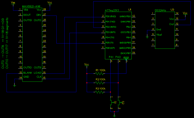
So, here the final schematic:
It’s the first time I used the ATtiny2313, but AVR-GCC is a great tools so.. To program this little stuff, I used the in-circuit programming, check out tuxgraphics doc for more infos about the whole stuff.
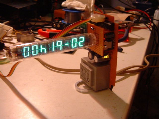
That’s fine, but does it look great ? ;)
Hum, yeah ! ;)
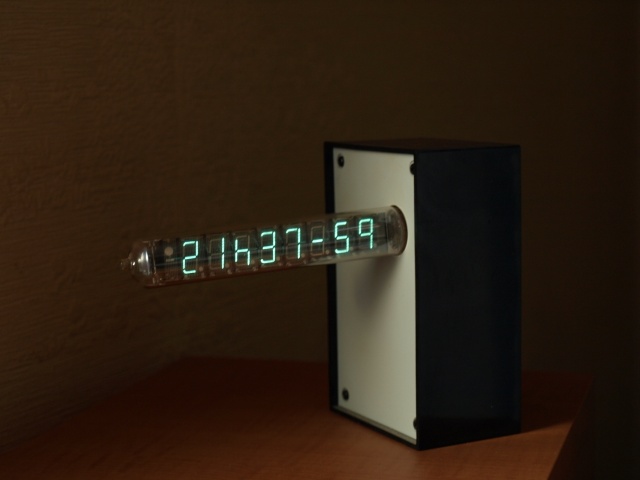
Here the (quite) finished product
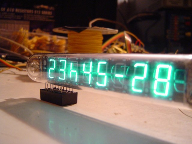
And if you look closer at the VFD:
DAMN! i wish i could make something cool like that, thats totally sweet. a glow in the dark way-cooler-than-LED clock
very nice!
well done!
can you post a photograph of the print with the SMD-chip? I am interested in the way that you connected that chip to the rest of the board.
tnx
Kees
The SMD-chip use a adapter. This adapter is solder to the veroboard. I used some "wrapping wire" to connect the adapater to the vacuum and 4 wires between the mainboard and this one. I will try to make de picture soon. (Check out the video, you will see part of that part).
Bye
Looks great! The tgz file just expands to one file. I can kinda see it in word, but not very well. Any hints? (I have ordered some tubes through shady ebay guys, we’ll see if I get them)
Graffy: The tgz file a Unix file. You can unzip it, with the original winzip. You will get a .tar that winzip should can open too. (If you have cygwin installed try: a "tar xvfz iv-clock.tgz". If yu really have trouble with that, send me a mail, I will drop you a .zip
I used Gschem for the schematic…
And to finish, if enought people are interested I can will produce some PCB.
Hey! Thanks for being so fast… a zip would be great… Us mechanical engineers shy away from this "unix" you speak of.
anyone wanna make me one? :-P
If anyone want’s one of this, please get in contact with me. I just bought 12 tubes of this type and (obviously…) don’t need them all. I don’t want to make a profit out of this. Just cut the costs and avoid having to store 10 tubes.
Juan Cubillo
as i remember better to use AC for heater to provide uniform brightness
Yes AC for heater is better, but this won’t work on MAX6921 (no neg input) ..
Another stuff, the song on the video is from Lonah (not Anabase)
Hi,
Thanks for your attention !
The descompacted archieve "iv18-clock" opens at Word-XP , but it is very confuse ( the schematic is mixed with the microcontroller code and all text is full of unicode and asc caracters )
Have you the microcontroller´s program in a separated text ?
Sorry for my english ! i´m from Brazil
Thanks
Jordan
Jordan please open the file with Winzip, as it’s archive compressed file..
Bye
Super! I’m interested in the PCB, what would one piece cost?
Jkx
I’m still confused. The entire schematic/circuit consists of the power supply circuit and the uC controller section (max921,attiny2313 and the ds32khz)? Anything else (besides the tube)?
What was the reason not using a wallwart? Do you have a copy of the spec for the IV-18 tube and could I get a copy of it?
I’m not an EE, but with such a low component count it would not be too diffcult to build one of these, just programming the attinywould be my hurdle.
Thank you for sharing your design/
Charles
I have the same problem with the TAR.
I would appreciate a .zip too if possible.
Any news on the pcb design ? If it ever gets designed im interested in some.
Thanks for sharing
Stef
I’ve just built up a version of this clock and it looks great and works very well.
However, I made a few mods to suit the components I had on hand:
– It uses a 9V DC plug pack.
– Because of this, it uses a switchmode boost converter to generate ~40V for the VFD anodes.
– I used a MAX787 for the 5V power supply, because that’s what I had on hand.
– I’ve used an ordinary watch crystal, trimming capacitor and a CD4060 in place of the DS32KHZ. When the DS32KHZ I have on order arrives, I’ll change back to your design since it will be more accurate.
I’ve used your software, which works really well. I only had to change the segment (font) and digit arrays to suit my wiring of the IV-18 tube.
However, I did notice what I think is an error on the schematic diagram. Namely, that the clock output from the DS32KHZ should go to pin 8 (PD4/T0) on the ATTiny2313, not pin 6 (PD2/INT0) as it is drawn above.
Before making this change the clock advanced the seconds very slowly and sporadically. Now it works perfectly. However, this change might only have been required because I am using a different clock generator, as noted above.
Thanks for taking the time to post up this design. It’s a really neat project.
Luc
Good news Spook79 :)
I changed the clock a couple of times, so perhaps there is a bug in. I need to post more photos on this clock too.
Hello
Ive just started building this cool clock and Im new to the AVR chip programming
Is the only file I need to program the Attiny2313 main.hex?
All other files were just for your testing and not necesary for me?
thanx for anyy input
is there any way to see that the clock circuit works, without the iv-18
Ive got the IV all lit up, but no pulse
how to test the attiny2313
I want to be like Dr Frankenstein
"ITS ALIVE!!!!!!!!!!!!!!!!!"
is there an output from the attiny that I could visibly check an on off on off motion
brivapor, please be a little more precise. Feel free to contact me over IRC or MSN to talk.
Bye
Hi Jkx
Ive started building your clock and notice in the schematics that on the Attiny, pin 10 is usually grounded and pin 20 is usually Vcc, is your schematics correct in this regard or should I add pin 10 and 20
also is that a (not)Vcc in the pin 1 reset?
Hello jkx. I have bought itron IV-18. I want to make a clock like you have. But I´m not electromechanic. I thought, that I make PCB and plug the parts, but I found that I must programate Attiny 2313. It is unbeatable problem for me. I realy don´t know nothing about this dilemma.
Can you tell me some advices?
PS: I can´t open “iv18-clock.gsch” . What is it in this file? PCB image? I have eagle software and it can´t open this file.
Thanks for answer. My mail is rimmerak@gmail.com
Sorry for my english, Im from czechrepublic.
Hi Rimmerak,
To program the Tiny2313 you can use a simple parallel wringler.
Please check out this : http://www.scienceprog.com/simplest-128-atmega-programmer/
For the .gsch file, this is a Geda software file : http://www.gpleda.org/
Hope this helps.
Why the schemmatic does not match to the code? Wrong input of 32kHz, wrong WFD wirings. Wery angrying and more hours spending project of nothing. Do not recomending this!
Download
You will find a complete archive file[[[[ here]]]]], it contains:
All the sources need to program the ATtiny
All the schematics to build you own ;)
download file here is not file
update please..
fules: This is a file, believe me ! … read other comments you will understand ..
Does somebody has de code in something other then a .gsch file .
Because i’m currently working with windows and gpleda does’nt work on this .
Please if someone could help me
This is a really great project. I have 10 of the IV-18 tubes ready, but am having real trouble finding the other ICs. The MAX6921 VFD driver and the DS32KHz are really hard to source in the UK.
Would be really great to have a seller (maybe eBay) that has packs of each component for this build.
At the moment, I am looking to get some parts from the US, and the rest from 2 different UK suppliers.
Would love to hear from anyone else that has built (or is building) one of these.
Alex
Hi,
I’d like your 10 spares please :) £20 . anyhow if your a stinge you can ask maxim for 5 samples of 6921 just dont take the piss and only ask once every 6 months. I couldn’t find anything else near as perfect. I used a PIC b’casue thats my way, anyone having problems with accurate time I suggest u get a RTC (also maxim sample) so it can keep time indep. off a v2-3bat
Cheers for the inspiration
i cant open the gsch programm in windows
pleas help