
After my nixie clock, I decided to build a new one based on a old VFD vacuum tube. In fact, the brother of a friend (which live in Ukrainia) give me a bag of tubes. Beside I already have a little set of this kind, I discover the IV-18. This one, is really big, and perfect for a clock.
Here a little pic of this big guy:
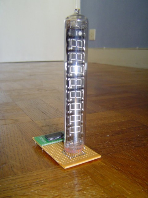
As you can see this is quite large, and really nice looking. I spent a little time to figure out, how to make it working (reading russian isn’t really easy). After sending a mail to the NeonNixie group, Chris help me to fix my issue.
So here the IV-18 pinouts:
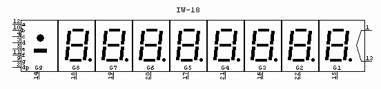
And the values:
- power supply for a digit : 20v-30v (if not muxed)
- power supply in muxed (for the 9 digit): 50v-70v
- the filament: 4.3v-5v at 100mA
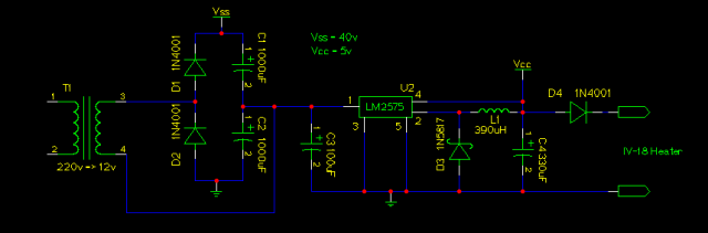
The first step was to build the PSU
Power Supply
I want to build a small clock which feet in a small box without the use of a wallmart (external) transformer. So I went to my junk box, and found a small 2x6v – 350mA transformer. Hum, after a little test, I found that using this with a voltage doubler, I can get around 40v. Beside I should use 50v in muxed, I discover that 40v is far enought, and It will save the VFD life. (even if this kind of VFD should live at least 10 years without issue)
That fine.. but I need some 5v too. My first thought was to simply plug a 7805 in the middle of the voltage doubler… That works fine, except the 7805 is really hot, and need a large heatsink. So I decided to use a switching PSU based on a LM2575.
Here the final power supply. (as you can see, I added a diode the filament PSU to avoid it to glow too much)
Here’s a pic:
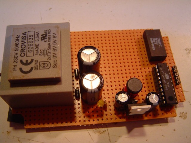
You can see
- the transformer
- the two caps and diodes from the doubler
- the LM2575 and its parts
- the ATtiny2313 (micro-controller used to do the logic)
- the DS32kHz (32.768kHz Temperature-Compensated Crystal Oscillator)
- and the little plug I used to do the in-circuit programming.
Warning don’t miss the next post !! (more pictures)
Check out the next article for the finished product :)
I was looking at your project and I just wanted to tell you it is kick ass I am going to try it at home. Hopefully I won’t have any issues:)
Nice project, that’s really awesome! Where can I pick up some of those big ass tubes?
If you want to buy some IV-18 ask URALS-SHOP on Ebay. This guys is really serious, offer good price, and provide best quality tubes.
Bye Bye
I just purchased some of these tubes on ebay and am trying to test light a segment. From the information you posted it seems the metal mesh grid in front of the segment must be powered to positive 5v and each segment to be lit must have positive 20-30v put to it. Where is the negative hooked up then? Also is there a heater in these tubes or what is the common long wire in the back of the tube? Thanks for any help you may give.
Jkx,
Thanks for the response! I still am slightly confused, what pins on the VFD does the heater output in the schematic hook up to? Also the 20V is AC and the 5v is DC correct?
Heater pin: 1 – 13 (5v AC or DC, I used DC)
And 20v DC
hello ! great project ! congratulations !
i would like to make this one , but i need a .zip code program file …
can you send it to me in .zip to my e-mail address ? please ?
thanks a lot
Jordan
Jordan, I guess you should read the next page as it contain the file (in tgz but winzip can open it)
Wowcolors check the complete schematic on the second post.
A quick test:
Each PSU (5 and 20v) share the same ground. (The negative for this tube is the filament)
Hi,
Very neat project.
I too got my hands on some of these tubes, and I downloaded the files (for which: my thanks!)
But how does that µController get its programming on it?
Could you elaborate on this?
Cheers
Patrick
I use a AVR ISP for that (In Circuit Programming ..) Chech out Google, most ISP are simple and cost nothing ..
Hi I know that on ebay.co.uk you should find seller dan_oka , he have 1000′s of them for sale price is around 1-2 GBP each or 500 GBP for 500 pcs
I noticed that you called it a wallmart (external transformer). I think you could change this to a “WallWart” lest you anger the mighty Wallmart Company ;-) I noticed your use of DC to drive the filament if you are using a buck regulator and DC how about placing a resistive load across C4 and placing the heater across L1? I am trying to develop a clock that drives EL panels and have similar issues.
Hey, I found your nice project while thining about how I should realize my voltage sources for my own vfd-Tubes-project.
Think I’m stupid, but why do you get 40V DC, if you use a Voltage doubler with 12V AC?