Firefox 2.0 on Debian

As everybody knows the mozilla team just released the latest version of Firefox (ver: 2.0). This will take a little time until, it will fall in the Debian. But you can find an optimized build for here called Swiftfox in debian package. So let’s go ;)

And last, but not least the optimized version, go quite really fast ;)

Enjoy

IV-18 VFD vacuum Russian Clock (part 2)

In the previous article, I have study the way to power this large VFD, now we gonna take a look closer at the logic itself. We need to drive a lot of bits (8+9) at ~40v. After a little googling, I discover that Allegro still sell some VFD drivers, but they are really hard to buy, and only provide a small amout of outputs (in DIP package).

Ok .. so I decided to use a Maxim VFD driver: the MAX6921:

  • 20 outputs
  • 4 wire serial-interface
  • supply voltage: 8v / 76v
  • 40mA output

The main issue is that it only exist in a SO package, so I need to use a little adapter to use MAX6921 on a veroboard .. (I bought this at my local store, but they cost twice the price of the MAX)

The next step, is the clock itself. For my nixie clock, I tested several stuff like 50hz (mainlines) sync, or external oscillator but this isn’t accurate enought. This time, I decided to use a plain old DS32kHz crystal oscillator. I’m pretty sure this won’t loose a second in a week ;)

To finish the clock, I need a micro-controller, as I need a really little amout of IO (2 for buttons, 4 for the VFD driver, and 1 for the oscillator), I decided a ATtiny2313 could do the job perfectly and give me the enought room for other stuff (like a LDR for automatic dimming)

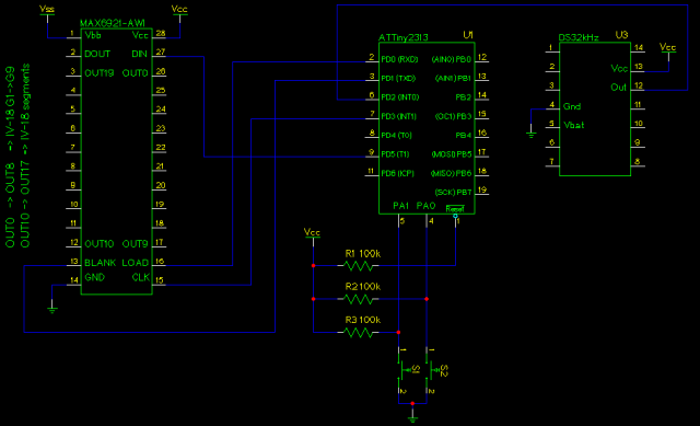
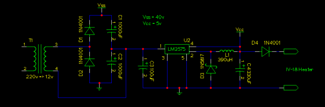
So, here the final schematic:

http://jkx.larsen-b.com/photos/VFDProjects/iv_18_u.sized.png

The full schematic

It’s the first time I used the ATtiny2313, but AVR-GCC is a great tools so.. To program this little stuff, I used the in-circuit programming, check out tuxgraphics doc for more infos about the whole stuff.
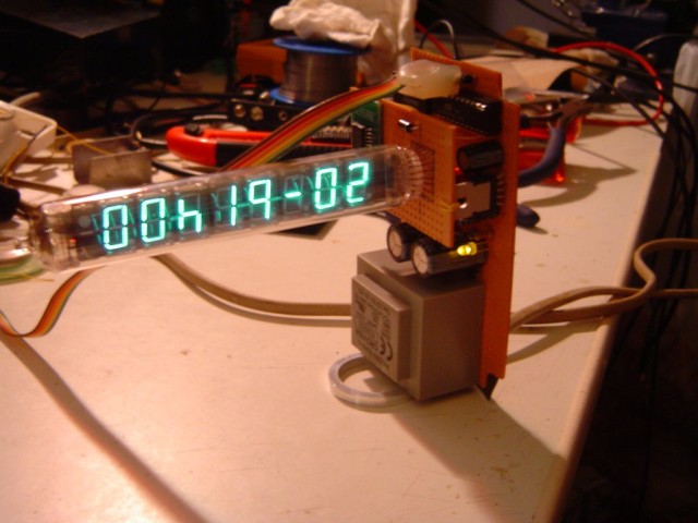
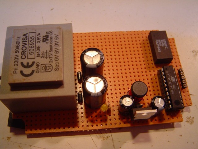
That’s fine, but does it look great ? ;)

Hum, yeah ! ;)

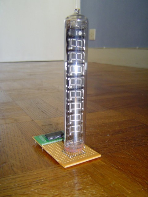
Here the (quite) finished product

http://jkx.larsen-b.com/photos/VFDProjects/dsc02406.sized.jpg

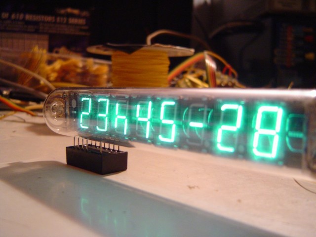
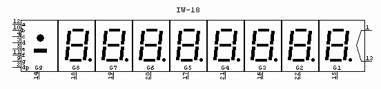
And if you look closer at the VFD:

http://jkx.larsen-b.com/photos/VFDProjects/DSC02324.sized.jpg
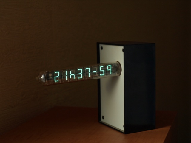
And the finished product :

Download

You will find a complete archive file here, it contains:

  • All the sources need to program the ATtiny
  • All the schematics to build you own ;)

/Enjoy

IV-18 VFD vacuum Russian Clock (part 1)

After my nixie clock, I decided to build a new one based on a old VFD vacuum tube. In fact, the brother of a friend (which live in Ukrainia) give me a bag of tubes. Beside I already have a little set of this kind, I discover the IV-18. This one, is really big, and perfect for a clock.

Here a little pic of this big guy:

http://jkx.larsen-b.com/photos/VFDProjects/DSC02312.sized.jpg

As you can see this is quite large, and really nice looking. I spent a little time to figure out, how to make it working (reading russian isn’t really easy). After sending a mail to the NeonNixie group, Chris help me to fix my issue.

So here the IV-18 pinouts:

http://jkx.larsen-b.com/photos/VFDProjects/iv_18_pinouts.png

And the values:

  • power supply for a digit : 20v-30v (if not muxed)
  • power supply in muxed (for the 9 digit): 50v-70v
  • the filament: 4.3v-5v at 100mA

The first step was to build the PSU

Power Supply

I want to build a small clock which feet in a small box without the use of a wallmart (external) transformer. So I went to my junk box, and found a small 2x6v – 350mA transformer. Hum, after a little test, I found that using this with a voltage doubler, I can get around 40v. Beside I should use 50v in muxed, I discover that 40v is far enought, and It will save the VFD life. (even if this kind of VFD should live at least 10 years without issue)

That fine.. but I need some 5v too. My first thought was to simply plug a 7805 in the middle of the voltage doubler… That works fine, except the 7805 is really hot, and need a large heatsink. So I decided to use a switching PSU based on a LM2575.

Here the final power supply. (as you can see, I added a diode the filament PSU to avoid it to glow too much)

http://jkx.larsen-b.com/photos/VFDProjects/iv_18_psu.sized.png

Here’s a pic:

http://jkx.larsen-b.com/photos/VFDProjects/DSC02402.sized.jpg

You can see

  • the transformer
  • the two caps and diodes from the doubler
  • the LM2575 and its parts
  • the ATtiny2313 (micro-controller used to do the logic)
  • the DS32kHz (32.768kHz Temperature-Compensated Crystal Oscillator)
  • and the little plug I used to do the in-circuit programming.

Warning don’t miss the next post !! (more pictures)

Check out the next article for the finished product :)